Antennas have a consistent set of primary specifications, or parameters, comprising: Frequency, Gain, Bandwidth, HPBW, Sidelobes, Polarisation, Cross Polar, Return Loss, and VSWR. See below for an explanation of each of these specifications:
FREQUENCY
 Most antennas are designed to operate efficiently within a 10% bandwidth.
Therefore, 2.5GHz ±5% means a frequency of 2.375 to 2.625GHz, which is a 250MHz bandwidth.
For further example, at 10GHz, an antenna will operate at between 9.5 to 10.5GHz.
GAIN
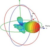
 Antennas passively increase the radiated power by concentrating it into certain directions. The gain of an antenna is a measure of its directionality. Gain is measured in dB (isotropic) or dBi and is usually expressed in dB or dBi relative to an isotropic source (equal in all directions). Antennas are not 100% efficient and have internal losses.
The gain of an antenna includes these losses. Therefore, Gain = Directivity – Internal losses.
Gain is the additional signal strength that the antenna provides in one direction at the expense of signal strength in other directions. An antenna is normally a passive device providing gain by directing the energy to a required pattern, resulting in a higher signal strength in one direction and lower in other directions.
BANDWIDTH
 The bandwidth of an antenna is the range of frequency where the antenna is operating effectively. Typically, our antennas have a nominal 10% bandwidth.
This may increase or decrease depending on the antenna and the performance required. It is important to specify the exact bandwidth that is needed.
Specifying L-band, for example, is not sufficient. L-band covers 1 to 2GHz; much larger than at 10% bandwidth.
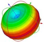
The diagram to the right shows Gain relative to isotropic pattern of antenna.
HPBW – Half Power Beam Width
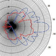
Omni Antennas – A dipole is the simplest type of omni-directional antenna. It has 360° azimuth coverage; the energy is squeezed from top and bottom to provide gain on the horizon. The elevation pattern is measured by taking a vertical cut through the beam.
The antenna's beam width is defined by the angle over which the radiated energy falls to half its peak level. This is known as the Half Power Beam Width (HPBW), or the -3dB point. This will apply to the elevation pattern whilst the azimuth beam width will be 360°.
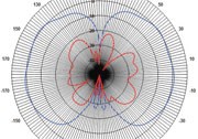
Directional and Sector Antennas – Energy is directed from vertical and horizontal sides to produce a directional lobe or sector beam. For directional and sector antennas, azimuth and elevation HPBW are specified separately.
|
 HPBW azimuth pattern |
SIDE-LOBES
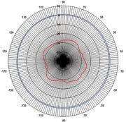
 In antenna engineering, side-lobes are the lobes of the radiation pattern that are not the main beam. An antenna radiation pattern is more commonly called a beam pattern.
The power density in the side-lobes is generally much less than that in the main beam. Side-lobe levels are measured in dBs relative to the peak of the main beam. It is possible to control side-lobe levels, depending on the application.
POLARISATION
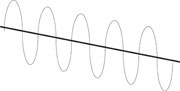
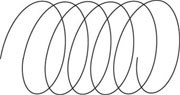
All electromagnetic radiation is polarised. The figures below show the electric (E) vector in a propagating wave for various types of polarisation. The polarisation of an antenna describes the orientation of its electrical field (i.e its E-Plane).
The polarisation can be linear or circular. Linear polarisation is usually vertical or horizontal. Dual polar antennas can produce vertical and horizontal polarisation via separate ports. A further extension of this are dual slant antennas; these are essentially the same as dual vertical and horizontal antennas but with the polarisation rotated by 45°. Circular polarisation is produced when the E-plane of the antenna spins. Depending on the direction of spin, the polarisation is right or left.
 |
 |
 |
|
Vertical Polarisation |
Horizontal Polarisation |
Circular Polarisation |
Antennas are never perfectly polarised. Cross polar is a measure of how much energy is in the plane perpendicular to the E-plane or opposite hand of circular polarisation. It is typically quoted relative to the peak gain of the antenna.
RETURN LOSS and VSWR
Return Loss is the amount of signal that is reflected by the antenna at the connector. This is expressed either as the relative level of the return signal in dB, or in terms of the Voltage Standing Wave Ratio (VSWR) present on the input to the antenna, as a result of the reflection. Return loss and VSWR are related.


